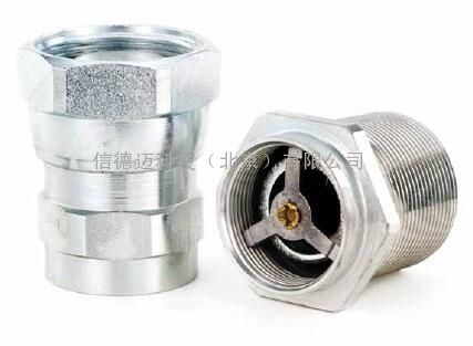
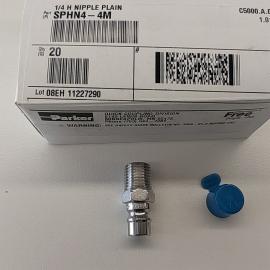
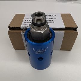
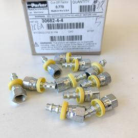
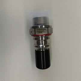
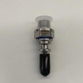
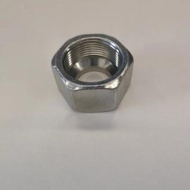
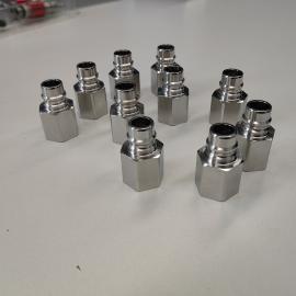
- EATON伊顿5400系列低空气包体制冷剂快速接头
详细信息
品牌:eaton aeroquip 型号:5100-S5-8 加工定制:否 安装形式:快换接口 种类:多款供选 材质:碳钢 接管口径:12 EATON Aeroquip 5400 Series Low Air Inclusion Refrigerant
EATON Quick Disconnect Couplings
EATON伊顿5400系列低空气包体制冷剂快速接头
Eaton 5400 Series Low Air Inclusion Refrigerant Quick Disconnect Couplings
EATON伊顿5400系列低含气量产品线专为空调、制冷剂、气体和流体输送应用而设计的制冷快速接头。符合SAE J2064性能和R134a。Eaton’s 5400 Series low air inclusion product line is designed for air conditioning, refrigerant, gaseous and fluid transfer applications。Meets SAE J2064 Performance with R134a。
Features
Guardian Seal Plating for Outstanding Corrosion Resistance
Multi-Refrigerant, including R134, R1234yf, R407C and others
Sizes 4, 8, 12 and 16
产品特性:
- 铜焊或螺纹端部连接,便于在管道或软管上安装。
- 用于低流体损失和空气夹杂的管状阀结构
- 螺纹连接设计允许在压力下连接和断开
- 可选隔板安装的锁紧垫圈和防松螺母标准配置
- 标准密封材料:氯丁橡胶
- 密封电镀,具有优异的耐腐蚀性
- 零下40度 to +135度 (-40oF to +275oF)
- 尺寸Sizes 4, 8, 12 and 16 (1/4,1/2, 3/4 and 1 inch)
- 适用于多种制冷剂包括,包括R134、R1234yf、R407c等
规格参数
(in) (bar) (psi) (bar) (psi) (bar) (psi) (bar) (psi) (in./Hg) (lpm) (gpm) cc- max- cc.max-
1/4 207 3,000 621 9,000 172 2,500 52 750 28 8 2 .10 .05
1/2 121 1,750 359 5,200 121 1,750 52 750 28 53 14 .10 .10
- 48 700 145 2,100 48 700 45 650 28 132 35 .30 .10
1 48 700 145 2,100 48 700 21 300 28 284 75 .50 .20
Applications & Markets
产品市场应用
- Mobile Air Conditioning and Refrigerant
移动空调和制冷剂
mm (in) mm (in) mm (in) mm (in) mm (in)
5400-S2-4 Male 1/4 No Adapter 1 27.4 (1.08) 21.1 (.83) 19 (.75) - - - -
5400-S5-4 Female 1/4 No Adapter 2 28.7 (1.13) 21.1 (.83) 16.0 (.63) 19 (.75) - -
5400-S2-8 Male 1/2 No Adapter 1 34.8 (1.37) 32.0 (1.26) 29.0 (1.14) - - - -
5400-S5-8 Female 1/2 No Adapter 2 40.6 (1.60) 33.0 (1.30) 26.0 (1.02) 30.0 (1.18) - -
5400-S2-12 Male - No Adapter 1 44.2 (1.74) 46.4 (1.83) 41.0 (1.61) - - - -
5400-S5-12 Female - No Adapter 2 55.1 (2.17) 45.0 (1.77) 35.0 (1.38) 41.0 (1.61) - -
5400-S2-16 Male 1 No Adapter 1 46.5 (1.83) 53.0 (2.10) 48.0 (1.89) - - - -
5400-S5-16 Female 1 No Adapter 2 61.1 (2.41) 56.0 (2.20) 45.0 (1.77) 50.0 (1.97) - -
Dimensions – SAE 37° (JIC) (Dimensional reference only)
Part Number Coupling Body Port Dimensions Buna-N Type Size Size Thread Type Fig- A B Hex Hex
*Couplings must be ordered by components as shown on page 147- mm (in) mm (in) mm (in) mm (in) mm (in)
5410-S17-4-4* Male 1/4 7/16 7/16-20 SAE 37° (JIC) 3 47.8 (1.88) 21.1 (.83) 19 (.75) - - 16.0 (.63)
5410-S14-4-4* Female 1/4 7/16 7/16-20 SAE 37° (JIC) 4 49.0 (1.93) 21.1 (.83) 16.0 (.63) 19 (.75) 15.7 (.62)
5410-4-4* Complete 1/4 7/16 7/16-20 SAE 37° (JIC) 5 89.9 (3.54) - - - - - - - -
5410-S17-6-4* Male 1/4 9/16 9/16-18 SAE 37° (JIC) 3 48.0 (1.89) 21.1 (.83) 19 (.75) - - 16.0 (.63)
5410-S14-6-4* Female 1/4 9/16 9/16-18 SAE 37° (JIC) 4 49.3 (1.94) 21.1 (.83) 16.0 (.63) 19 (.75) 15.7 (.62)
5410-6-4* Complete 1/4 9/16 9/16-18 SAE 37° (JIC) 5 90.4 (3.56) - - - - - - - -
5410-S17-6-8* Male 1/4 9/16 9/16-18 SAE 37° (JIC) 3 55.4 (2.18) 31.8 (1.25) 29 (1.14) - - 25.4 (1.00)
5410-S14-6-8* Female 1/2 9/16 9/16-18 SAE 37° (JIC) 4 61.7 (2.43) 33.3 (1.31) 26 (1.02) 30 (1.18) 25.4 (1.00)
5410-6-8* Complete 1/2 9/16 9/16-18 SAE 37° (JIC) 5 107.4 (4.23) - - - - - - - -
5410-S17-8-8* Male 1/2 - .-16 SAE 37° (JIC) 3 57.9 (2.28) 31.8 (1.25) 29 (1.14) - - 25.4 (1.00)
5410-S14-8-8* Female 1/2 - .-16 SAE 37° (JIC) 4 64.3 (2.53) 33.3 (1.31) 26 (1.02) 30 (1.18) 25.4 (1.00)
5410-8-8* Complete 1/2 - .-16 SAE 37° (JIC) 5 112.8 (4.44) - - - - - - - -
5410-S17-10-12* Male - 7/8 7/8-14 SAE 37° (JIC) 3 69.9 (2.75) 46.5 (1.83) 41 (1.62) - - 35.1 (1.38)
5410-S14-10-12* Female - 7/8 7/8-14 SAE 37° (JIC) 4 80.3 (3.16) 45.7 (1.80) 35 (1.38) 41 (1.62) 35.1 (1.38)
5410-10-12* Complete - 7/8 7/8-14 SAE 37° (JIC) 5 135.4 (5.33) - - - - - - - -
5410-S17-12-12* Male - 1 1/16 1 1/16-12 SAE 37° (JIC) 3 72.6 (2.86) 46.5 (1.83) 41 (1.62) - - 35.1 (1.38)
5410-S14-12-12* Female - 1 1/16 1 1/16-12 SAE 37° (JIC) 4 83.1 (3.27) 45.7 (1.80) 35 (1.38) 41 (1.62) 35.1 (1.38)
5410-12-12* Complete - 1 1/16 1 1/16-12 SAE 37° (JIC) 5 140.7 (5.54) - - - - - - - -
5410-S17-16-16* Male 1 1 5/16 1 5/16-12 SAE 37° (JIC) 3 75.9 (2.99) 53.3 (2.10) 48 (1.89) - - 44.5 (1.75)
5410-S14-16-16* Female 1 1 5/16 1 5/16-12 SAE 37° (JIC) 4 89.7 (3.53) 56.9 (2.24) 45 (1.77) 50 (1.97) 44.5 (1.75)
5410-16-16* Complete 1 1 5/16 1 5/16-12 SAE 37° (JIC) 5 149.6 (5.89) - - - - - - - -
Above items must be ordered at the component level - see page 148-
5400 Series Low Air Inclusion Refrigerant
Dimensions – Braze Tubing Adapter (Dimensional reference only)
Part Number Coupling Body Tube O.D- Dimensions Neoprene Type Size Size Type Fig- A B Hex
*Couplings must be ordered by components as shown on page 147- mm (in) mm (in) mm (in) mm (in) mm (in)
5401-S17-4-4* Male 1/4 1/4 Braze Tubing Adapter 6 38.6 (1.52) 21.1 (.83) 19 (.75) - - 16.0 (.63)
5401-S14-4-4* Female 1/4 1/4 Braze Tubing Adapter 7 39.9 (1.57) 21.1 (.83) 16.0 (.63) 19 (.75) 16.0 (.63)
5401-S17-6-4* Male 1/4 3/8 Braze Tubing Adapter 6 38.6 (1.52) 21.1 (.83) 19 (.75) - - 16.0 (.63)
5401-S14-6-4* Female 1/4 3/8 Braze Tubing Adapter 7 39.9 (1.57) 21.1 (.83) 16.0 (.63) 19 (.75) 16.0 (.63)
5410-S17-6-8* Male 1/2 3/8 Braze Tubing Adapter 6 44.5 (1.75) 33.3 (1.31) 29 (1.14) - - 25.4 (1.00)
5401-S14-6-8* Female 1/2 3/8 Braze Tubing Adapter 7 50.8 (2.00) 33.3 (1.31) 26 (1.02) 30 (1.18) 25.4 (1.00)
5401-S17-8-8* Male 1/2 1/2 Braze Tubing Adapter 6 44.5 (1.75) 33.3 (1.31) 29 (1.14) - - 25.4 (1.00)
5401-S14-8-8* Female 1/2 1/2 Braze Tubing Adapter 7 50.8 (2.00) 33.3 (1.31) 26 (1.02) 30 (1.18) 25.4 (1.00)
5401-S17-10-12* Male - 5/8 Braze Tubing Adapter 6 62.7 (2.47) 45.7 (1.80) 41 (1.62) - - 35.1 (1.38)
5401-S14-10-12* Female - 5/8 Braze Tubing Adapter 7 73.2 (2.88) 45.7 (1.80) 35 (1.38) 41 (1.62) 35.1 (1.38)
5401-S17-12-12* Male - - Braze Tubing Adapter 6 62.7 (2.47) 45.7 (1.80) 41 (1.62) - - 35.1 (1.38)
5401-S14-12-12* Female - - Braze Tubing Adapter 7 73.2 (2.88) 45.7 (1.80) 35 (1.38) 41 (1.62) 35.1 (1.38)
5401-S17-16-16* Male 1 1 Braze Tubing Adapter 6 71.1 (2.80) 56.9 (2.24) 48 (1.89) - - 44.5 (1.75)
5401-S14-16-16* Female 1 1 Braze Tubing Adapter 7 84.8 (3.34) 56.9 (2.24) 45 (1.77) 50 (1.97) 44.5 (1.75)
Dust Caps and Dust Plugs Dust Cap Dust Plug
Dust Cap with Gasket Dust Plug with Gasket Body Size
5400-S6-8 5400-S8-8 1/2 5400-S6-12 5400-S8-12 - 5400-S6-16 5400-S8-16 1
Adapter SAE
37° (JIC) Adapter SAE 37° (JIC)
O-Ring Brass Steel Body Size Thread Tube O.D- Size
22546-12 202220-4-4B 202220-4-4S 1/4 7/16-20 1/4 22546-12 202220-6-4B 202220-6-4S 1/4 9/16-18 3/8 22546-17 -202220-6-8S 1/2 9/16-18 3/8 22546-17 202220-8-8B 202220-8-8S 1/2 .-16 1/2
22546-23 -22546-23 - 202220-10-12S 202220-12-12S - - 7/8-14 1 1/16-12 5/8 -
22546-28 - 202220-16-16S - 1 3/16-12 1
Adapter – Braze Adapter – Braze
22546-17 202208-8-8B - 1/2 7/8-20 1/2
2254617 202208-10-8B 202208-10-8S 1/2 7/8-20 5/8
22546-23 202208-10-12B 202208-10-12S - 1 1/4-18 5/8
22546-23 202208-12-12B - - 1 1/4-18 -
22546-23 202208-14-12B - - 1 1/4-18 7/8
22546-28 202208-14-16B - 1 1 19/32-20 7/8
22546-28 202208-16-16B - 1 1 19/32-20 1
22546-28 202208-18-16B - 1 1 19/32-20 1 1/8
22546-28 202208-20-16B - 1 1 19/32-20 1 3/16
22546-28 202208-22-16B - 1 1 19/32-20 1 1/4
Hose Fitting SAE 100R5- Dimensions Hose Fitting SAE 100R5 O-Ring Fitting Assembly Body Size Hose Size Thread D (O-Ring Required)
mm (in) 22546-12 487-4-4S 1/4 -4 1/2-20 23.4 (.92) 22546-12 487-4-6S 1/4 -6 1/2-20 24.4 (.96) 22546-17 487-8-6S 1/2 -6 7/8-20 24.4 (.96) 22546-17 487-8-8S 1/2 -8 7/8-20 26.9 (1.06)
22546-23 487-12-10S - -10 1 1/4-18 27.2 (1.07)
.Additional dash styles available-
5400 Series Low Air Inclusion Refrigerant 5400 Series Low Air Inclusion Refrigerant
For assemblies, order by components as shown by base number and dash (-) size below- Example, if a 5401-S14-10-12 is required, order as components, (1) 5400-S5-12, (1) 202208-10-12B Adapter and (1) 22546-23 O-Ring-
Assembly Part Number 5400-S2 Male Half Quantity 5400-S5 Female Half Quantity 202208-Brass Braze-On Adapter Quantity 202220-Steel 37- SAE Adapter Quantity 22546 O-Ring Quantity
5401-S14-10-12 -12 1 -10 -12B 1 -23 1
5401-S14-10-8 -8 1 -10 -8B -17 1
5401-S14-12-12 -12 1 -12 -12B 1 -23 1
5401-S14-16-16 -16 1 -16 -16B 1 -28 1
5401-S14-4-4 -4 1 -4 -4B 1 -12 1
5401-S14-6-4 -4 1 -6 -4B 1 -12 1
5401-S14-6-8 -8 1 -6 -8B 1 -17 1
5401-S14-8-8 -8 1 -8 -8B 1 -17 1
5401-S17-10-12 -12 1 -10 -12B 1 -23 1
5401-S17-10-8 -8 1 -10 -8B 1 -17 1
5401-S17-12-12 -12 1 -12 -12 1 -23 1
5401-S17-14-16 -16 1 -16 -16 1 -28 1
5401-S17-4-4 -4 1 -4 -4B 1 -17 1
5401-S17-6-4 -4 1 -6 -4B 1 -12 1
5401-S17-6-8 -8 1 -6 -8B 1 -17 1
5401-S17-8-8 -8 1 -8 -8B 1 -17 1
5410-12-12 -12 1 -12 1 -12 -12S 2 -23 2
5410-16-16 -16 1 -16 1 -16 -16S 2 -28 2
5410-4-4 -4 1 -4 1 -4 -4S 2 -12 2
5410-6-8 -8 1 -8 1 -6 -8S 2 -17 2
5410-8-8 -8 1 -8 1 -8 -8S 2 -17 2
5410-S14-10-12 -12 1 -10 -12S 1 -23 1
5410-S14-12-12 -12 1 -12 -12S 1 -23 1
5410-S14-16-16 -16 1 -16 -16S 1 -28 1
5410-S14-4-4 -4 1 -4 -4S 1 -12 1
5410-S14-6-4 -4 1 -6 -4S 1 -12 1
5410-S14-6-8 -8 1 -6 -8S 1 -17 1
5410-S14-8-8 -8 1 -8 -8S 1 -17 1
5410-S17-10-12 -12 1 -10 -12S 1 -23 1
5410-S17-12-12 -12 1 -12 -12S 1 -23 1
5410-S17-16-16 -16 1 -16 -16S 1 -28 1
5410-S17-4-4 -4 1 -4 -4S 1 -12 1
5410-S17-6-4 -4 1 -6 -4S 1 -12 1
5410-S17-6-8 -8 1 -6 -8S 1 -17 1
5410-S17-8-8 -8 1 -8 -8S 1 -17 1
Assembly Instructions/Component Part Numbers
Typical Male Coupling Half (S2)
Assembly Instructions
Steps:
1- After tubing or hose has been connected to adapters
1 and
12 , install O-Rings
2 and
11 - on adapters- Be sure O-Rings are not twisted-
2- Oil O-Rings
2 liberally with system fluid to prevent them from scuffing and tearing when coupling body is threaded on adapter-
3- S2 Half—Lubricate poppet face with system fluid- Insert poppet valve assembly
3 into body
4 - Tighten body 4 on adapter 1 - After body and adapter make metal-to-metal contact, tighten by rotating body
4 1/8” with respect to adapter
1 or torque per table value-
S5 Half—Oil O-Ring 9 - liberally with system fluid- Insert valve and sleeve assembly 10 into body
8 - Tighten body
on adapter
12 - After body and adapter make met-al-to-metal contact, tighten by rotating body 8 1/8” with respect to adapter
12 or torque per table value-
4- Coupling Connection—Lubricate gasket seal
5 on 5400-S2 half with system fluid- Thread union nut
on 5400-S2 half- Tighten union nut to torque values shown in table- Be sure S2 and S5 bodies do not rotate during connection-
Component Part Numbers
Item Dash Size –4 Number O.D- Tube Size 1/4”–3/8”
Typical Female Coupling Half (S5)
Bulkhead Mounting—S2 Half
Install lock washer
6 on S2 half- Insert S2 half through bulkhead, and tighten jam nut
7 so that lock washer teeth are fully compressed-
NOTE: Lock washer 6 must be between hex of S2 half and bulkhead-
Maximum Bulkhead Thickness
Body Lock Washer Lock Washer Size Installed Not Used
- .206 .256
- .136 .203
- .232 .292
1 .101 .161
Torque Values
Recommended torque values in ft- lbs., are listed below-
Adapter to Body
Dash Braze Type Non-braze Type S2 Half Size or Aluminum Steel or Brass to S5 Half
–4 6–8 12–15 10–12
–8 15–20 35–45 35–37
–12 35–40 45–55 45–47
–16 50–60 55–65 65–67
.IMPORTANT: Generous lubrication is required for all gaskets and O-Rings- Use refrigeration oil only when used in refrigerant system-
–8 –12 –16 Line 1/4”–5/8” 5/8”–7/8” 7/8”–13/8” Ref-
Typical Male Half 1
1 Tubing Adapter 202208–*–4 202208–*–8 202208–*–12 202208–*–16 2
2 O-Ring 22546–12 22546–17 22546–23 22546–28 3
3 Poppet Valve Assembly 5400–S20–4 5400–S20–8 5400–S20–12 5400–S20–16 4
4 Body 5400–17–4S 5400–17–8S 5400–17–12S 5400–17–16S 5
5 Gasket Seal 22008–4 22008–8 22008–12 22008–16 6
6 Lock Washer 5400–54–4S 5400–54–8S 5400–54–12S 5400–54–16S 7
7 Jam Nut 5400–53–4S 5400–53–8S 5400–53–12S 5400–53–16S 8
Typical Female Half 9
8 Union Nut and Body Assembly 5400–S16–4 5400–S16–8 5400–S16–12 5400–S16–16 10
9 O-Ring FF91178–10 FF91178–112 FF91178–116 FF91178–214 11
10 Valve and Sleeve Assembly 5400–S19–4 5400–S19–8 5400–S19–12 5400–S19–16 12
11 O-Ring 22546–12 22546–17 22546–23 22546–28 13
12 Tubing Adapter 202208–*–4 202208–*–8 202208–*–12 202208–*–16 14
*Specify O.D- Tubing size of adapter required in 16th of an inch- Example: –4 coupling with 3/8” O.D- tubing is 6/16 or –6- Part number is then 202208–6–4-
-
 信德迈科技(北京)有限公司期待您的来电!
13910122694
EATON伊顿5400系列低空气包体制冷剂快速接头
页面价格仅供参考,具体请联系报价价格 价格电议,您可以向供应商询价得到该产品价格- 产品型号:5100-S5-8
- 品 牌:eaton aeroquip
- 所 在 地:北京
- 更新日期:2024-04-25
合计:1台总价:电议(联系我时,请说明是从谷瀑网看到的,谢谢!)内容声明:谷瀑为第三方平台及互联网信息服务提供者,谷瀑(含网站、客户端等)所展示的商品/服务的标题、价格、详情等信息内容系由店铺经营者发布,其真实性、准确性和合法性均由店铺经营者负责。谷瀑提醒您购买商品/服务前注意谨慎核实,如您对商品/服务的标题、价格、详情等任何信息有任何疑问的,请在购买前通过谷瀑与店铺经营者沟通确认;谷瀑上存在海量店铺,如您发现店铺内有任何违法/侵权信息,请在谷瀑首页底栏投诉通道进行投诉。信德迈科技(北京)有限公司 电话:010-84282935 手机:13910122694 地址: 北京朝阳区望京街10号望京SOHO-T1-C座2115室
 扫一扫,手机浏览